RDS Surveyor is being developed by Christophe Jacquet, a radio ehtusiast.
Run RDS Surveyor 2 now in your browser!
Project links:
Hardware modifications
Overview
RDS Surveyor needs a source of RDS data (a bitstream at 1187.5 bit/s). One way to achieve this is to use a radio receiver USB dongle such as the RTL-SDR. Another way is to hook a classical radio set to your computer, and that is what this page describes. You need to proceed in two stages:
-
Modify an existing radio set, so that the discriminator output (often caled “multiplex” or MPX) is available outside of the box.
What's this “multiplex” signal? Well, FM radio involves modulating (and demodulating) some low frequency (LF) signal. In the first years of FM broadcasting, this LF was directly an audio frequency (AF) signal, with bandwidth 19 kHz. But over time, several components were added to the LF signal: a second channel for stereo, which is double-sideband-amplitude modulated around 38 kHz, and RDS, which is phase-modulated around 57 kHz. Therefore, the LF signal is now a multiplex of several components. In particular, the audio signal available on the headphone output is not the multiplex signal. You need to tap the multiplex signal from the printed circuit board. Generally, it is available near the discriminator chip. You can try to guess, but undoubtedly it is better if you can find the datasheet of the discriminator, or, even better, the service manual of your radio set. -
Take the multiplex signal through an RDS demodulator chip.
There are several such chips available, for instance the TDA7330 from STMicro, or the SAA6579 from NXP Semiconductors. These are quite outdated chips, but they have been widely used for homemade RDS receivers. There are now more recent alternatives, that should work in the same way. The output of the demodulator chip must be fed into the computer, for instance using a sound card or a serial port. Due to the phasing out of serial ports, a more viable alternative would be to use USB, which I tried. However, I was confronted with a lot of noise coming from the 24 MHz oscillator necessary for USB operation. It caused cross-talk in the FM tuner, centered around 96 MHz. Good shielding should help overcome these difficulties, but shielding isn't the greatest asset of homemade circuits, is it? So I used a TDA7330, plus an optocoupler for galvanic insulation, which inverts signals, and feeds them into the sound card. Currently in RDS Surveyor, the only real-time input method corresponds to this setup. However, due to the modular nature of RDS Surveyor (see the design document), one can easily and quickly write a new input method (aka BitReader) for their own setup (and contribute the code!).
Example of radio set modification for multiplex output: Sangean PR-D1
The PR-D1 was available from Sangean at the end of the 1990s. The service manual of the PR-D1 is now available online.
The PR-D1 has its own RDS decoder chip, an SAA6579 from Philips Semiconductors (now NXP). I suppose that one could tap the RDS bitstream directly from this chip, but I found easier and safer to use the multiplex output instead.
The first thing to do is to remove the back cover of the radio set. First remove the two screws at the back (do not remove the antenna screw!). After that, only “clips” hold the back cover in place. Look at the service manual, press inwards at the places where clips are located. Be careful, the clips are fragile, and I personaly broke a few of them (which is not so much of an issue, the back cover still remains in place without any problems).
After removing the back cover, you have he main circuit board in from of you. At the bottom left-hand corner, there is a wide horizontal connector, which contains the two pins of interest for us: the ground and the multiplex signal.
- The ground, called « GND » on the schematic diagram, is the third pin from the right.
- The multiplex signal, called « RDS in » on the schematic diagram, is the third pin from the left.
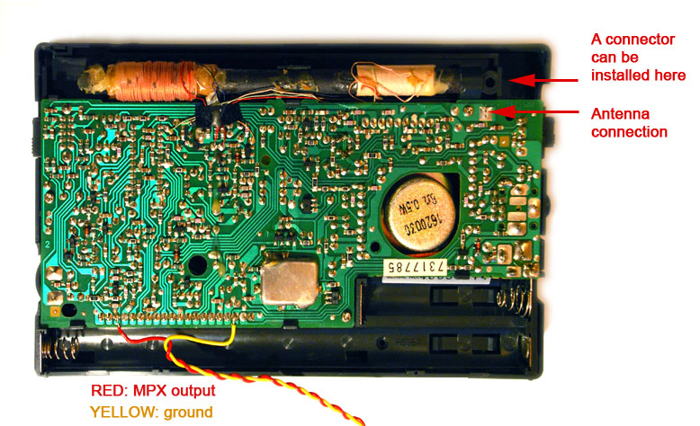
Solder wires to these pins, and there you go! Personaly, I used an audio shielded cable after the first test showed above, and connected it to a .1"-jack socket on the front panel to take the signal out of the radio. There is room for a jack socket at the top left-hand corner of the front panel (as seen from outside), just near the antenna connection.
My RDS demodulator circuit
My RDS demodulator uses a TDA7330 from STMicro and an optocoupler (TLP521-4). The output of the optocoupler is level-adapter to be fed into a sound card.
Schematic:
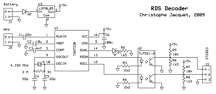
The optocoupler outputs are open-drain. They are connected to the medium point of a voltage divider. The sound card output is at this point, too. In this way, if the sound card's input impedance is infinite (no leak current), then the voltage is either 0 (low) or 1.5kΩ / (10kΩ + 1.5kΩ) ⨯ 5V = 0.65V. This is the right level for the line input of a sound card, that accept voltages up to 0.7V. In practice the input impedance won't be infinite, so the voltage will be lower than 0.65V, but still high enough for the decoder to work. In any case, the voltage will be between 0V and 0.65V, so the sound card should not be damaged.
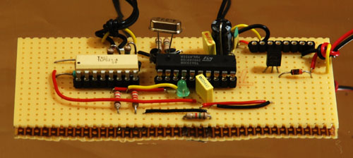
My prototype on Veroboard:
Datasheets:
Please note
This circuit works fine for me. However, if you with to use it, you do it at your own risk. I could not be held responsible of any damage caused to any person or equipment (radio set, computer, etc.).